#include <maxentropychannel.h>
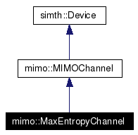
Inheritance diagram for mimo::MaxEntropyChannel:

Public Member Functions | |
| MaxEntropyChannel (int deviceID, DeviceSystemIntf *system, const simth::PropertyList &pl) | |
| ~MaxEntropyChannel () | |
| void | getTransfer (int relative_time, MatrixFreqSignal &transfer) const |
| void | transmit (const VectorTimeSignal &insym, VectorTimeSignal &outsym) |
| int | roundTimeToSamples (double value) const |
| Converts the real value "Delay" into a number of steps on the time scale. | |
| virtual void | refresh () |
| Called to refresh the entries of the matrices. | |
| void | set_normfactor () |
| Sets the normfactor if power normalization is requested. | |
| void | getImpulseResponse (int relative_time, MatrixTimeSignal &impulse) const |
| writes the impuls response matrix at a certain time | |
| double | get_angle () const |
| double | get_delay () const |
| double | get_gauss () const |
| Returns a complex gaussian distributed variable. | |
| virtual void | print (std::ostream &os) const |
| Reimplementation of print. | |
Protected Member Functions | |
| void | updateInputLengths () |
| void | updateOutputLengths () |
Related Functions | |
| (Note that these are not member functions.) | |
| propertylist_MaxEntropyChannel (not_a_function) | |
In the frequency domain the channel matrix of a MIMO System is given as:
![\[ \textbf{H}(f)= \left(\begin{array}{ccc} h_{11}(f) & \cdots & h_{1t}(f) \\ \vdots & \ddots & \vdots \\ h_{r1}(f) & \cdots & h_{rt}(f) \\ \end{array}\right) \]](form_12.png)
Merouane Debbah assumes that the channel matrix is calculated as followed:
![\[ \textbf{H}_{r\times t}=\frac{1}{\sqrt{ss_1}} \Phi_{r\times s} \textbf{P}^\textbf{r} \Theta_{s\times s_1}\odot \textbf{D}_{s\times s_1} \textbf{P}^\textbf{t} \Psi_{s_1\times t} \]](form_13.png)
 and
and  contain the amplitudes of the different steering vectors of the propagation paths. In this simulation we assume them to be one. The
  matrix contains information about phase shifts which are a result of the different angles of departure from the transmitter. The
  matrix gives information about the paths that arrive at the receiver. Beside the phase shifts it also takes into account the doppler effect, because whe assume that the receiver is moving with a cvertain speed.
The  is an i.i.d. Gaussian matrix linking the scattering environment at the transmitter side with the one at the receiver side. The
  matrix stores the delays for those links.
![\[ \Theta_{s\times s_1}= \left(\begin{array}{ccc} \theta_{11} & \cdots & \theta_{1s} \\ \vdots & \ddots & \vdots \\ \theta_{s1} & \cdots & \theta_{ss_1} \\ \end{array}\right) \hspace{3em} \textbf{D}_{s\times s_1}(f)= \left(\begin{array}{ccc} e^{-j2\pi f\tau_{11}} & \cdots & e^{-j2\pi f\tau_{1s_1}} \\ \vdots & \ddots & \vdots \\ e^{-j2\pi f\tau_{s1}} & \cdots & e^{-j2\pi f\tau_{ss_1}} \\ \end{array}\right) \]](form_20.png)
The  and the
  matrix are multiplied element-wise (
 ).
).
The whole  matrix can be written as:
![\[ \textbf{H}(f,\eta)=\frac{1}{\sqrt{ss_1}} \left(\begin{array}{ccc} e^{j(\phi_{11}+2\pi \frac{f_c u_{11}^rv_r}{c} \eta)} & \cdots & e^{j(\phi_{1s}+2\pi \frac{f_c u_{1s}^rv_r}{c} \eta)} \\ \vdots & \ddots & \vdots \\ e^{j(\phi_{r1}+2\pi \frac{f_c u_{r1}^rv_r}{c} \eta)} & \cdots & e^{j(\phi_{rs}+2\pi \frac{f_c u_{rs}^rv_r}{c} \eta)} \\ \end{array}\right) \hspace{0.5em} \Theta_{s\times s_1} \hspace{0.5em} \odot \hspace{0.5em} \textbf{D}_{s\times s_1} \hspace{0.5em} \left(\begin{array}{ccc} e^{j\psi_{11}} & \cdots & e^{j\psi_{1t}} \\ \vdots &\ddots & \vdots \\ e^{j\psi_{s_11}} & \cdots & e^{j\psi_{s_1t}} \\ \end{array}\right) \]](form_23.png)
In the time domain the impulse response from a transmitting antenna  to a receiving antenna
  is given by
![\[ h_{nm}(\tau,t) = \frac{1}{\sqrt{s_{1}s}} \sum_{k=1}^{s_{1}} \sum_{p=1}^{s} \theta_{pk} e^{j\psi_{km}} \cdot \delta(\tau - \tau_{pk})\cdot e^{j(\phi_{np} +2\pi \frac{f_c u_{np}^rv_r}{c} \eta)} \]](form_26.png)
After estimating each entry of the impulse response matrix the received signal will be calculated as followed:
![\[ y(t) = \sqrt{\frac{\rho}{t}}\int{\textbf{H}_{r\times t}(\tau)x(t-\tau)d\tau + n(t)} \]](form_27.png)
|
||||||||||||||||
|
Constructor
|
|
|
|
|
||||||||||||
|
Determines channel transfer factors. An ideal estimation of the channel transfer function is performed. This means, the exact values Implements mimo::MIMOChannel. |
|
||||||||||||
|
Transmits a symbol sequence over the channel. Implements mimo::MIMOChannel. |
|
|
Converts the real value "Delay" into a number of steps on the time scale.
|
|
|
Called to refresh the entries of the matrices.
Reimplemented from simth::Device. |
|
|
Sets the normfactor if power normalization is requested.
|
|
||||||||||||
|
writes the impuls response matrix at a certain time
|
|
|
This function returns uniform distributed random angles by using an object of the class UniformRng. |
|
|
A function to get random delays, it uses an object of the class DelayProfile. The delays have a negative exponential or a uniform distribution, to be set in the .par file |
|
|
Returns a complex gaussian distributed variable.
|
|
|
Reimplementation of print.
Reimplemented from mimo::MIMOChannel. |
|
|
Reimplemented from mimo::MIMOChannel. |
|
|
Reimplemented from mimo::MIMOChannel. |
|
|
These are the properties of class MaxEntropyChannel . This list is auto-generated from the XML-Devicelist of this device by means of an XSLT transformation script. Description of this device in the XML file: Note that this class also has the Properties of its base classes. The direct base class is mimo::MIMOChannel ; direct link to its propertylist should be propertylist_MIMOChannel(). The list below usually includes the properties that have been inherited from the base classes; the properties which belong only to this class can be found at the end of this list.
|
 1.4.1
1.4.1